


.svg)
Operating Instructions for AIR Series IE2 Three-Phase Asynchronous Electric Motors EKVIVES

Operating Instructions for AIR Series IE2 Three-Phase Asynchronous Electric Motors (EKVIVES)
EKVIVES AIR series IE2 efficiency class electric motors are reliable three-phase asynchronous machines designed to drive various industrial equipment such as pumps, fans, compressors, machine tools, and more.
These instructions outline essential guidelines for preparation, installation, connection, and maintenance to ensure long-term and safe operation.
1. General Information & Standards
EKVIVES AIR series electric motors are manufactured in accordance with TU U 27.1-37502259-008:2024 and comply with national and international standards: DSTU EN 60034-1, DSTU EN 60034-5, DSTU EN 60034-7, DSTU EN 60947-4-2, and DSTU EN 61000-3-3.
Package Contents:
Electric motor assembly — 1 pc.
Passport / Operating Manual — 1 pc.
Electric motor assembly — 1 pc.
Passport / Operating Manual — 1 pc.
2. Operating Conditions & Safety Requirements
Operating Environment:
Ambient Temperature: -40 °C to +40 °C.
Duty Cycle: Continuous (S1). Note: Motors are not intended for S3/S4 intermittent duty without prior agreement.
Ambient Temperature: -40 °C to +40 °C.
Duty Cycle: Continuous (S1). Note: Motors are not intended for S3/S4 intermittent duty without prior agreement.
Safety Precautions:
Installation and maintenance must be performed only by qualified personnel.
Before starting work, ensure the power supply is disconnected and the shaft has completely stopped.
Properly isolate live parts and keep the terminal box closed.
Use eye bolts for lifting and moving the motor.
The motor housing can become hot during operation — avoid accidental contact.
Installation and maintenance must be performed only by qualified personnel.
Before starting work, ensure the power supply is disconnected and the shaft has completely stopped.
Properly isolate live parts and keep the terminal box closed.
Use eye bolts for lifting and moving the motor.
The motor housing can become hot during operation — avoid accidental contact.
3. Preparation for Initial Start-Up
Visual Inspection: Inspect the motor for physical damage to the frame, fan cover, or terminal box.
Depreservation: Remove transport locking rings (if fitted) and rotate the shaft manually — it must rotate freely without binding or unusual noise.
Insulation Resistance Check:
Measure winding insulation resistance using a 500 V DC megohmmeter. At +25 °C, the minimum acceptable resistance is calculated as:
Visual Inspection: Inspect the motor for physical damage to the frame, fan cover, or terminal box.
Depreservation: Remove transport locking rings (if fitted) and rotate the shaft manually — it must rotate freely without binding or unusual noise.
Insulation Resistance Check:
Measure winding insulation resistance using a 500 V DC megohmmeter. At +25 °C, the minimum acceptable resistance is calculated as:
R=20*U/(1000+2P) MOm
(where U is nominal voltage [V] and P is power [kW]).
Insulation resistance must be at least 0.5 MOm.
De-energize (discharge) windings immediately after testing.
Important: For every 20 °C increase in temperature, the acceptable resistance threshold is halved.
Winding Drying: If insulation resistance is below standard, dry the windings in an oven with drain plugs removed: 12–16 hours at +90 °C, followed by 6–8 hours at +105 °C.
Insulation resistance must be at least 0.5 MOm.
De-energize (discharge) windings immediately after testing.
Important: For every 20 °C increase in temperature, the acceptable resistance threshold is halved.
Winding Drying: If insulation resistance is below standard, dry the windings in an oven with drain plugs removed: 12–16 hours at +90 °C, followed by 6–8 hours at +105 °C.
4. Wiring Diagrams & Starting Methods
The terminal box contains 6 winding terminals and 1 grounding screw. Ground the motor frame securely according to local electrical regulations.
Starting Methods:
Direct-on-Line (DOL) or Star-Delta (Y / $\Delta$) Starting:
When using Star-Delta starting, the supply voltage must match the motor's rated voltage in Delta ($\Delta$) connection.
Direction of Rotation:
Phase order L1, L2, L3 provides clockwise rotation (viewed from the shaft end). To reverse rotation, swap any two line leads. Pay attention to the rotation direction arrow on the fan cover (if present).
Direct-on-Line (DOL) or Star-Delta (Y / $\Delta$) Starting:
When using Star-Delta starting, the supply voltage must match the motor's rated voltage in Delta ($\Delta$) connection.
Direction of Rotation:
Phase order L1, L2, L3 provides clockwise rotation (viewed from the shaft end). To reverse rotation, swap any two line leads. Pay attention to the rotation direction arrow on the fan cover (if present).
5. Mounting & Alignment
Foundation: Mount the motor on a rigid, level, and solid foundation to eliminate vibration.
Shaft Alignment: For direct coupling, ensure precise alignment of motor and driven equipment shafts. Misalignment causes vibration and premature bearing wear.
Belt Drive: Motors with belt drives must be mounted on tension rails for belt adjustment.
Fitting Components: Remove anti-corrosion coating and apply grease to the shaft before pressing on pulleys or couplings. Use pullers for removal and heat components for assembly. Unauthorized disassembly during the warranty period is prohibited!
Foundation: Mount the motor on a rigid, level, and solid foundation to eliminate vibration.
Shaft Alignment: For direct coupling, ensure precise alignment of motor and driven equipment shafts. Misalignment causes vibration and premature bearing wear.
Belt Drive: Motors with belt drives must be mounted on tension rails for belt adjustment.
Fitting Components: Remove anti-corrosion coating and apply grease to the shaft before pressing on pulleys or couplings. Use pullers for removal and heat components for assembly. Unauthorized disassembly during the warranty period is prohibited!
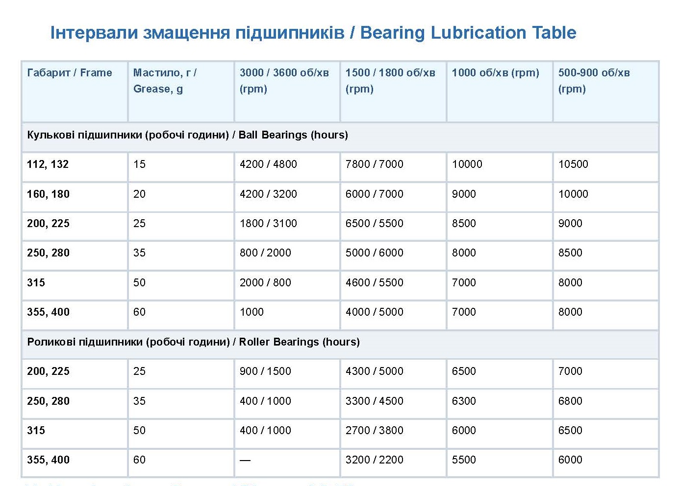
6. Maintenance & Bearing Lubrication
For long service life, perform regular maintenance:
Keep the frame and fan cover clean from dust and debris.
Check V-ring seals, fastener tightness, and bearing noise/vibration.
Lubrication Intervals:
2-pole motors (3000 rpm): Every 10,000 – 20,000 operating hours.
4+ pole motors (1500 rpm and lower): Every 20,000 – 40,000 operating hours.
2-pole motors (3000 rpm): Every 10,000 – 20,000 operating hours.
4+ pole motors (1500 rpm and lower): Every 20,000 – 40,000 operating hours.
7. Storage & Transportation
Storage: Store in dry, dust-free areas free from vibrations and corrosive vapors
. Coat shaft extensions and flanges with anti-corrosion grease and manually rotate the shaft periodically . Connect anti-condensation heaters if storing in humid environments . Transportation: Lock roller bearings with transport locking devices during transit to prevent raceway damage
.
8. Disposal & Recycling
At the end of service life, dismantle and sort components for recycling:
Aluminum: Rotor, terminal box (select models)
. Cast Iron / Steel: Frame, end shields, covers, shaft
. Copper: Stator winding
.

