Mounting Configurations for AIR Series Electric Motors
The AIR series (Asynchronous, General Industrial Purpose) electric motors are highly versatile and can be manufactured in a wide range of mounting configurations, according to the standards of GOST 2479 (IM system).
Here is a complete list of possible mounting configurations for AIR motors with explanations.
Mounting Configurations for AIR Series Electric Motors
All the IM codes listed below assume the use of a straight (cylindrical) shaft, which is standard for the AIR series. Unless otherwise specified, the motor has a single shaft end.
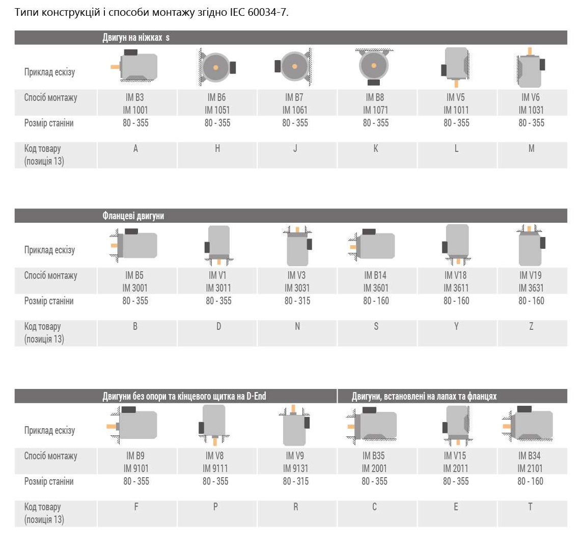
1. Foot-Mounted Configurations (Mounting on a Horizontal Base)
This is the most common mounting method, where the motor is fixed to a foundation or frame using cast feet on the housing.
IM Code
CENELEC Designation
Description
Shaft Position
IM 1081
IM B3
Standard foot-mounted configuration. The motor is fixed by feet to a horizontal surface.
Horizontal
IM 1011
IM V6
Foot-mounted, but installed vertically.
Shaft pointing down
IM 1031
IM V5
Foot-mounted, but installed vertically.
Shaft pointing up
IM 1002
IM B6
Foot-mounted. The motor is mounted on a side wall, with feet on the side.
Horizontal
IM 1062
IM V7
Foot-mounted. The motor is mounted on a side wall.
Shaft pointing down
IM 1052
IM V8
Foot-mounted. The motor is mounted on a side wall.
Shaft pointing up
2. Flange-Mounted Configurations (Mounting on a Shield or Gearbox)
The motor is mounted using a flange located on the front end shield.
A. With Large Flange (Flange diameter is larger than the motor housing)
IM Code
CENELEC Designation
Description
Shaft Position
IM 3081
IM B5
Standard flange-mounted configuration. Mounted using a large flange.
Horizontal
IM 3011
IM V1
Flange-mounted.
Shaft pointing down
IM 3031
IM V3
Flange-mounted.
Shaft pointing up
B. With Small Flange (Flange diameter is equal to or smaller than the motor housing)
IM Code
CENELEC Designation
Description
Shaft Position
IM 3681
IM B14
Mounted using a small flange (for compact installation).
Horizontal
IM 3611
IM V18
Small flange.
Shaft pointing down
IM 3631
IM V19
Small flange.
Shaft pointing up
3. Combined Configurations (Feet + Flange)
The most versatile option, allowing the motor to be fixed both to the base and to the flange of the driven mechanism.
A. With Feet and Large Flange
IM Code
CENELEC Designation
Description
Shaft Position
IM 2081
IM B35
Standard combined configuration. Has both feet and a large flange.